Wall Geometry and Loads
This option opens a tab window in which definition of wall geometry, loads on the wall or on the backfill can be entered. This option opens a tab window in which definition of wall geometry, loads on the wall or on the backfill can be entered.

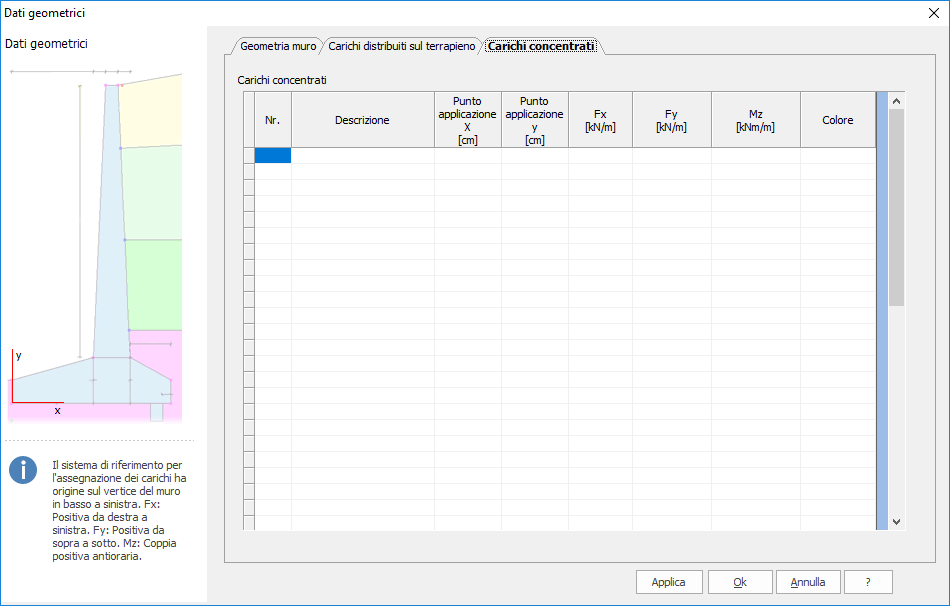
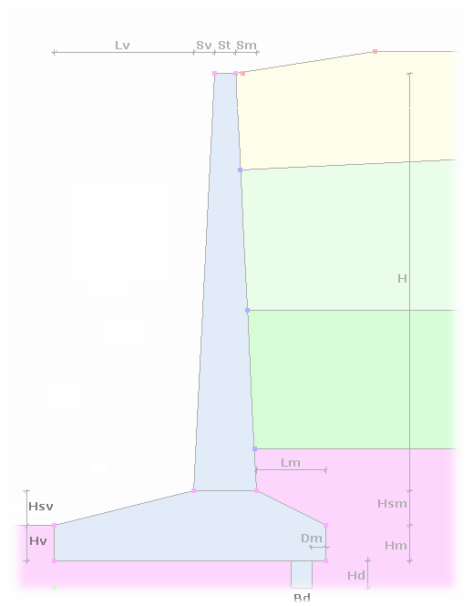
Wall Geometry Wall geometry is entered by wall element. Thus a pane each is devoted to wall stem, wall footing, footing key, and flying shelf. It is also possible to define the uphill side of the wall as a number of steps, whose individual geometry is then declared. Within the same window, there where no supporting piles are present, a pane enables the presence of a lean mix base below the footing to be specified, that is taken into consideration for slide limit state verification.
Loads may be modeled on the project as:
Loads may be specified either by acting on the respective tool bar icon or by invoking "Wall Geometry and loads" from the Data Menu.
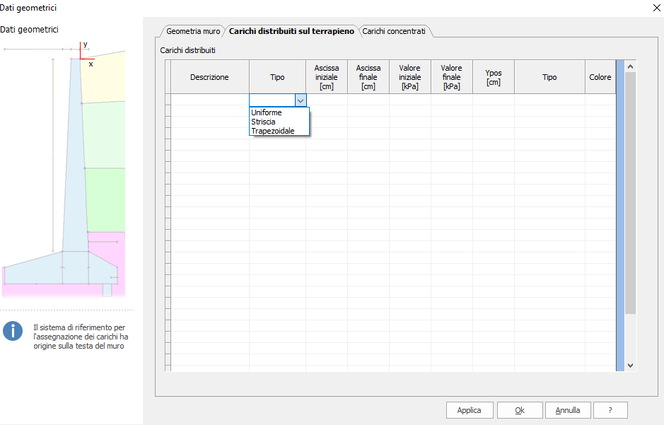
Distributed loads
The extent of the load is defined by the start and end abscissa values; the load value can be constant or variable. The depth indicates its placement in relation to the stem head.
Even multiple loads can be defined and their action combined during the calculation according to specified permutation factors.
The effect of loads on the active thrust is only considered if this is located within the failure wedge.
Point loads
Such loads can be modeled according to the following conventions below:
Multiple point loads can also be defined and their action combined during the calculation according to specified permutation factors.