Boundary conditions
The boundary conditions must be assigned differently for the two calculation phases. In the first phase, the boundary conditions of a classic finite element analysis are assigned, such as hinges on the lower edge and rollers with axis perpendicular to the edge, along the lateral surfaces. In the second phase, these constraints must be supplemented by absorbing boundaries, which have the function of limiting the effects of the reflection of the seismic waves at the edges of the model, reflections that have only a numerical character but that in reality do not occur on site.
To apply the constraints, select the nodes of interest (button "Select group of nodes" from the Tools panel) and then click on "Add constraints".
Phase 1
The purpose of this phase is to compute the initial stress state of the problem under examination. In this phase, the boundary conditions are assigned as indicated below.
Along the lower edge of the model, hinges are applied. In other words, displacements are prevented both in the horizontal and in the vertical direction.
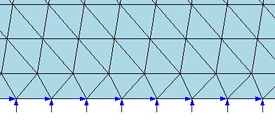
Phase 1: constraints applied along the lower edge of the model
Along the lateral edges, rollers with axis perpendicular to the edge are applied instead. In essence, the displacements in the horizontal direction are prevented, while displacements in the vertical direction are allowed.
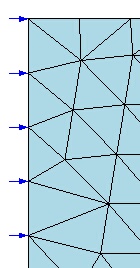
Phase 1: constraints applied along the lateral edges of the model
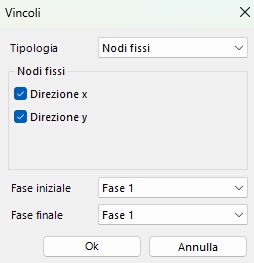
After clicking the "Add constraints" button, the displacements of phase 1 must be assigned by selecting "Fixed nodes" from the drop-down menu. This type of constraint must be assigned only with reference to Phase 1.
Phase 2
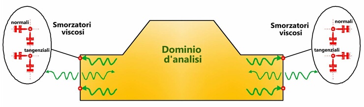
In this phase the input accelerogram is assigned and the response spectrum is computed. As an effect of the accelerogram, seismic waves are generated that propagate within the model. These waves are reflected and amplified at the edges of the model. Since these edges do not exist on site, the seismic waves generated by reflection at the edges have no physical meaning. For this reason, it is necessary to define suitable constraints, aimed at eliminating, or at least reducing, these effects. To this end, in the second phase, absorbing boundaries must be assigned along the edges of the model, whose purpose is precisely to limit the reflection effects at the edges.
To do this, after selecting the edge nodes on which the constraints are to be applied from the Tools panel, and after clicking on "Add constraints", select the "Absorbing boundaries" type.
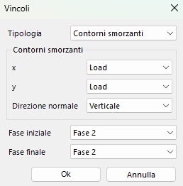
The absorbing boundaries, on the other hand, must be assigned only to Phase 2. The boundaries can be of type Free or Load: in the Free case the node is free to move in the direction in which it was assigned, without considering the absorbing effect; conversely, Load means that the node will move conditioned by the damping effect.
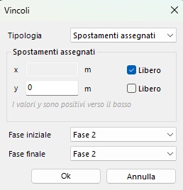
In addition, the displacements of the lower edge of the model must also be constrained. Specifically, the displacements in the vertical direction must be prevented. This constraint can be assigned as indicated previously for Phase 1. Alternatively, the same constraint conditions can be applied by selecting the constraint type "Assigned displacements", as shown in the following figure.
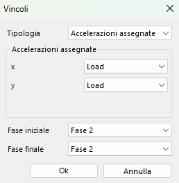
Finally, since in the second phase a seismic input will be assigned along the lower edge of the model, the latter must be prepared for the application of an accelerogram. To this end, after selecting the lower-edge nodes and "Add constraints", assign the "Assigned accelerations" type, as shown in the following figure. The assignment of the accelerogram is described in the dedicated section.
The following figure summarises the schematisation of the Phase 2 boundary conditions just described.

Phase 2: constraints applied along the edges of the model